ชุดเกจวัดความดันตำแหน่ง yd series
Cat:มาตรวัดความดัน
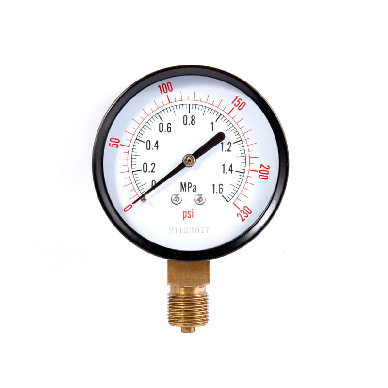
รุ่น: yd40 yd50 yd60 yd75 yd100 yd150 ◆ร่างกายหลักของเครื่องมือคือมาตรวัดความดั...
ดูรายละเอียด

Pressure measurement is fundamental to safe and efficient industrial operations, but measuring a single pressure point only tells part of the story. In many critical systems — from HVAC air handling units to hydraulic circuits and chemical processing plants — what matters most is the difference in pressure between two points. That's precisely what a differential pressure gauge is designed to measure. Understanding how this instrument works, why it's necessary, and where it's applied can make a significant difference in how well you maintain and troubleshoot the systems that depend on it.
A differential pressure gauge is an instrument that measures the pressure difference between two separate points in a system and displays that difference as a single reading. Unlike a standard gauge that measures pressure relative to atmospheric pressure (gauge pressure) or absolute vacuum (absolute pressure), a differential pressure gauge connects to two process points simultaneously — a high-pressure port and a low-pressure port — and outputs the mathematical difference between the two values.
This difference, often written as ΔP (delta P), carries enormous diagnostic and operational value. It can reveal how much resistance a filter has accumulated, how fast a fluid is flowing through a pipe, whether a pump is performing correctly, or whether a heat exchanger is fouling. The gauge itself does not care what the individual pressures are — only the gap between them — which is why it can be used across an extraordinarily wide range of pressures and applications by simply selecting the appropriate sensing range.
At its most fundamental level, a differential pressure gauge works by exposing two sides of a sensing element to two different pressures and measuring the mechanical or electrical response to the force imbalance. The sensing element — the physical component that reacts to the pressure difference — is the heart of the instrument, and its design determines the gauge's accuracy, range, and suitability for different media.
When high pressure is applied to the high-pressure port and a lower pressure to the low-pressure port, the sensing element deflects or deforms in proportion to the difference. This deflection is then converted into a readable output — either a needle movement on a dial face in mechanical gauges, or a voltage or current signal in electronic transmitters. The scale on the display is calibrated specifically to represent the pressure differential rather than absolute pressure, so a reading of zero means both ports are at equal pressure, regardless of the actual pressure level in the system.
Different gauge designs use different internal architectures, but the following components are common across most mechanical differential pressure gauges:
The diaphragm is the most widely used sensing element in differential pressure gauges. It is a thin, flexible disc — typically made from stainless steel, Hastelloy, or other corrosion-resistant alloys — that is clamped between two pressure chambers. High pressure is applied to one side, low pressure to the other, and the diaphragm flexes toward the low-pressure side in proportion to the pressure difference. This flexion is mechanically linked to the gauge pointer through a lever and gear assembly, driving the needle across the calibrated dial. Diaphragm gauges are suitable for liquids, gases, and viscous media, and can be manufactured with wetted materials suited to corrosive or hygienic applications.
Some differential pressure gauges use a dual Bourdon tube arrangement, where each tube is connected to one of the pressure ports and the mechanical outputs of both tubes are subtracted through a differential linkage. This design is more common in high-pressure applications where diaphragm deflection becomes too small to measure accurately. Bourdon tube designs tend to be more robust under high static pressures and are often found in hydraulic and high-pressure gas systems.
A capsule is essentially two diaphragms welded together at their edges to form a sealed chamber. In differential capsule gauges, one side of the capsule is exposed to the high-pressure process and the other to the low-pressure reference. Capsule elements are highly sensitive and are preferred for measuring very small differential pressures — often in the range of a few millibars — making them the standard choice in HVAC filter monitoring and clean room pressure control applications.
The mechanical movement translates the small physical deflection of the sensing element into a rotary motion that drives the pointer needle. A rack-and-pinion or sector-and-pinion gear set amplifies the tiny diaphragm movement into a full-scale pointer sweep — typically 270 degrees of arc across the dial face. The dial is printed with a scale in units of pressure differential such as Pa, mbar, kPa, psi, or inches of water column (inWC), depending on the application and regional standard.
The market offers several distinct types of differential pressure gauges, each optimized for different measurement ranges, media, and installation environments. Selecting the wrong type is one of the most common causes of premature gauge failure or inaccurate readings.
| Type | Sensing Element | Typical Range | Best Application |
| Diaphragm gauge | Metallic diaphragm | 0–600 mbar to 0–40 bar ΔP | Liquids, gases, general industrial |
| Capsule gauge | Welded capsule | 0–2.5 Pa to 0–600 Pa ΔP | HVAC filters, clean rooms, low ΔP gas |
| Piston gauge | Spring-loaded piston | 0–0.5 bar to 0–25 bar ΔP | Hydraulic systems, high static pressure |
| Manometer (U-tube) | Liquid column | Very low ΔP (Pa range) | Laboratory, low-pressure gas measurement |
| Electronic transmitter | Piezoelectric/capacitive cell | Wide range, user-configurable | Process automation, remote monitoring |
One of the most important and widely used applications of differential pressure measurement is inferring flow rate. When a fluid passes through a restriction — such as an orifice plate, a venturi tube, or a flow nozzle — its velocity increases and its static pressure drops in accordance with Bernoulli's principle. The faster the flow, the greater the pressure drop across the restriction. By measuring this pressure drop with a differential pressure gauge, engineers can calculate the volumetric or mass flow rate through the pipe.
This technique is known as differential pressure flow measurement and has been in use for over a century. It remains the most common flow measurement method in large-diameter pipes and high-pressure systems, particularly in oil and gas, water treatment, and power generation. The gauge is connected to tapping points on either side of the restriction element — upstream on the high-pressure port and downstream on the low-pressure port — and the ΔP reading is fed into a flow calculation formula or directly into a flow computer that outputs the final flow rate in engineering units.
A clean filter offers very little resistance to fluid or air flow, so the pressure difference across it is small. As the filter accumulates particulate matter and becomes blocked, resistance increases and the differential pressure rises. A differential pressure gauge mounted across a filter therefore acts as a direct, real-time indicator of filter condition — no guesswork, no scheduled replacement on arbitrary time intervals, just an objective measurement of actual restriction.
This application is ubiquitous across many industries and environments:
A differential pressure gauge can only provide accurate readings if it is installed correctly. Several practical installation factors commonly cause errors in field measurements, and understanding them prevents costly misdiagnosis of system problems.
While mechanical differential pressure gauges provide a local visual reading without any power supply requirement, electronic differential pressure transmitters offer significant advantages for modern automated systems. A transmitter uses a piezoelectric or capacitive sensing cell to convert the pressure difference into a 4–20 mA current signal or a digital output (such as HART, PROFIBUS, or Foundation Fieldbus) that can be fed directly into a distributed control system (DCS) or programmable logic controller (PLC).
Electronic transmitters offer remote monitoring capability, datalogging, alarm integration, and far greater accuracy — typically 0.05% to 0.1% of span compared to 1% to 2% for mechanical gauges. They are also configurable for multiple ranges without physical replacement. However, they require a power supply, are more expensive, and add complexity to the instrumentation loop. For many applications, a combination of both is used: a mechanical gauge for quick local indication and an electronic transmitter for control system integration and trending.
The differential pressure reading across a component is one of the most informative single measurements available in a process system. A rising ΔP across a filter signals progressive fouling. A falling ΔP across a pump indicates declining performance or cavitation. An unexpectedly low ΔP across a flow restriction may signal a bypass leak or a ruptured element. Because ΔP changes with physical conditions inside the system — not just at one measurement point — it provides insight into what is happening inside equipment that cannot be opened or inspected during operation.
For maintenance teams, integrating differential pressure monitoring into a predictive maintenance strategy reduces unplanned downtime significantly. Rather than replacing filters on a calendar schedule — which either changes them too early, wasting service life, or too late, allowing system damage — ΔP-based replacement ensures maximum filter utilization and protects downstream equipment from contamination. The same logic applies to heat exchangers, strainers, coalescers, and any component where fouling or restriction progressively develops over time. A well-chosen and correctly installed differential pressure gauge is, in many cases, the single most cost-effective instrument in the maintenance toolkit.

รุ่น: yd40 yd50 yd60 yd75 yd100 yd150 ◆ร่างกายหลักของเครื่องมือคือมาตรวัดความดั...
ดูรายละเอียด
รุ่น: YL40 YL50 YL60 YL75 YL100 YL150 ◆เครื่องมือประกอบด้วยมาตรวัดความดันทั่วไป...
ดูรายละเอียด
◆รุ่น: CYB100 CYB150 ◆แอปพลิเคชัน: ชุดเครื่องมือนี้เ...
ดูรายละเอียด
รุ่น: yxch100 yxch150 ◆แอปพลิเคชัน: เครื่องมือประเภทนี้เหมาะสำหรับการวัดความดันของ...
ดูรายละเอียด
◆รุ่น: YTX100B YTX150B ◆การใช้งาน: ชุดเครื่องมือนี้ใช้เป็นพิเศษในสภาพแวดล้อมโดย...
ดูรายละเอียด
1. ภาพรวม เครื่องส่งสัญญาณความดันนี้มีความไวสูง ความแม่นยำสูง และความสามารถในการป้องกันการโอเว...
ดูรายละเอียด
◆รุ่น: WSS-3 WSS-4 WSS-5 ◆แอปพลิเคชัน: เทอร์โมมิเตอร์ bimetal มีลักษณะของคว...
ดูรายละเอียด
◆รุ่น: WSZC-2 ◆ภาพรวม: เครื่องส่งสัญญาณประกอบด้วยเทคโนโลยีการรวมโมดูลวงจรขั้นสู...
ดูรายละเอียด
ระบบเตือนภัยประตูไม่มีน้ำเน้นการมีปฏิสัมพันธ์ระหว่างมนุษย์และเครื่องจักรโดยจัดการกับมลพิษของการดำ...
ดูรายละเอียด
เซ็นเซอร์อุณหภูมิ WZPK มีชื่อเสียงในเรื่องอายุการใช้งานที่ยาวนานและความมั่นคงที่ยอดเยี่ยมทำให้เป็...
ดูรายละเอียด


